What is Breadboard?
A breadboard is a device used to build and test electronic circuits without the need for soldering. It is a plastic board with a grid of holes in it, and each hole is connected to one or more other holes by a metal strip underneath the board. The holes are arranged in rows and columns, and the board usually has two sets of horizontal rails on each side, known as power rails, which are used to supply power to the components.
Electronic components, such as resistors, capacitors, and integrated circuits, can be inserted into the holes on the breadboard and connected together by inserting wires or jumper leads into the holes to make the desired connections. The components and wires can be easily rearranged as needed, making breadboards a useful tool for prototyping and experimenting with new circuit designs.
Breadboards are commonly used by hobbyists, students, and electronics professionals to build and test circuits before making a more permanent version on a printed circuit board (PCB). They are also used to teach electronics and circuit design in educational settings.
How do breadboards work, their components, and how to use them?
Breadboards are used to prototype and test electronic circuits without the need for soldering. They are made up of a plastic board with a grid of holes, and underneath the board, there are metal strips or wires that connect the holes in specific ways. These metal strips or wires are responsible for creating the electrical connections between the components.
On the breadboard, there are usually two columns of power rails, one for the positive voltage (Vcc) and one for the ground (GND). These power rails are used to provide power to the components in the circuit.
The power rails are connected to the metal strips or wires underneath the board, which are used to distribute power to the rest of the breadboard. Here’s a breakdown of the components and how they work:
The board:
The plastic board is usually made of white ABS plastic with a series of holes drilled into it. The holes are arranged in rows and columns to allow for easy placement of electronic components.
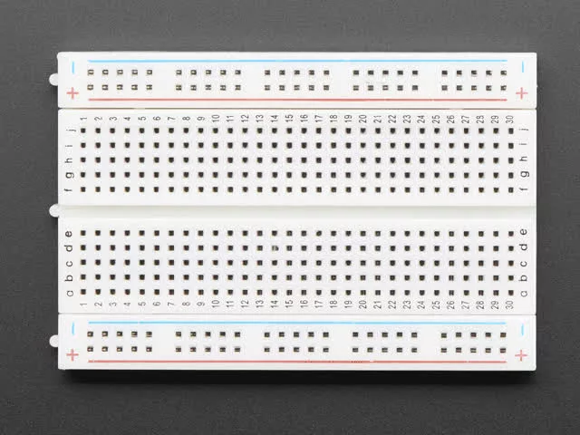
Power rails:
On each side of the breadboard, there are two rows of holes that run the length of the board. These are known as power rails and they are used to provide power to the components on the board. Typically, the top rail is used for positive voltage (Vcc) and the bottom rail is used for ground (GND).
Terminal strips:
The terminal strips are the long, vertical strips that run the length of the breadboard, and they provide a common connection between multiple holes. Components can be connected to each other or to the power rails by inserting wires or jumper leads into the holes.
Rows and columns:
The rows and columns of holes on the breadboard are connected by metal strips underneath the board. Each row is connected horizontally, and each column is connected vertically. The rows and columns are not connected to each other, which means that components connected in one row or column do not affect components in other rows or columns.
Common mistakes to avoid when using a breadboard
Here are some common mistakes to avoid when using a breadboard:
1. Placing components in the wrong holes: It’s important to make sure that components are inserted into the correct holes on the breadboard. Make sure to check the datasheet or schematic for the component before inserting it into the breadboard.
2. Forgetting to connect power: Make sure to connect power to the power rails on the breadboard. Without power, the components won’t work.
3. Using too much force when inserting components: It’s important to insert components gently into the holes on the breadboard to avoid damaging the board. If a component doesn’t fit, double-check to make sure you are inserting it into the correct holes.
4. Not using the correct type of wire: Solid-core wire is best for use with breadboards because it fits snugly into the holes. Using stranded wire or wire that is too thin can lead to poor connections or wires falling out of the breadboard.
5. Overloading the power supply: Breadboards are designed to handle low-voltage circuits. If you try to power a high-current device or circuit, you may overload the power supply and damage the components.
6. Using breadboards for high-frequency circuits: Breadboards are not ideal for high-frequency circuits as the parasitic capacitance between the strips and holes can cause unwanted noise and affect the performance of the circuit. In such cases, a dedicated PCB may be a better choice.
7. Crowding the breadboard: Avoid crowding the breadboard with too many components or wires as this can make it difficult to identify and troubleshoot problems. Use separate sections of the breadboard for different components and keep the wiring organized.
8. Not testing the circuit as you go: Test the circuit as you go by applying power to the breadboard and checking the behavior of the components. This can help you identify any problems early on and avoid wasting time on a circuit that won’t work.
Different types of breadboard connections:
Breadboards are commonly used to prototype and test electronic circuits. They allow for easy and quick construction of circuits without the need for soldering. There are several types of breadboard connections, each with its own advantages and disadvantages. Here are some common types of breadboard connections:
Solderless breadboards:
These are the most common type of breadboard and are designed for rapid prototyping. They consist of a plastic board with holes arranged in a grid pattern. The holes are connected to each other with metal strips underneath the board. Solderless breadboards are reusable and allow for easy modification of circuits.
Stripboard:
Stripboard is a type of breadboard that uses copper strips rather than holes to make connections. Components are placed on the copper strips and connections are made by soldering wires between them. Stripboard is more permanent than solderless breadboards but allows for more compact designs.
Prototyping breadboards:
These breadboards are designed for more advanced prototyping and experimentation. They have a larger number of holes and rows than solderless breadboards and may include features like built-in power supplies, voltage regulators, or a ground plane. Prototyping breadboards allow for more complex circuits to be built but are more expensive and less portable than solderless breadboards.
Terminal strip breadboards:
Terminal strip breadboards are similar to solderless breadboards, but they have terminal strips rather than metal strips underneath the board. Terminal strip breadboards are designed for permanent connections and are commonly used in industrial or commercial applications.
Breadboard modules:
These are pre-fabricated breadboard modules that allow for quick and easy construction of circuits. They are typically designed for a specific purpose, such as motor control or sensor interfacing. Breadboard modules are ideal for rapid prototyping and can be easily modified for different applications.
Understanding the different types of breadboard connections is important when choosing a breadboard for a particular project. Each type has its own advantages and disadvantages, and selecting the right type can help ensure the success of your project.
Conclusion:
This blog post explores the topic of breadboards and how they work. Breadboards are used for prototyping and testing electronic circuits without the need for soldering. The post explains the different types of breadboard connections, including solderless breadboards, stripboard, prototyping breadboards, terminal strip breadboards, and breadboard modules.
The post also covers the common components of a breadboard, such as the power rails, bus strips, and terminal strips, and provides tips for using a breadboard, including common mistakes to avoid.
- Ultimate Guide to Fintech Tools for Businesses 2026 - April 3, 2026
- Complete Cybersecurity Toolkit for SMBs in 2026 - March 31, 2026
- Best Password Managers for Personal and Business Use2026 - March 30, 2026


